
|
|
Configuration Database Project |
| Home | Computing | DAQ | Notes | Meetings | Subsystems | Search |
Keep in mind that the information you insert is for you, i.e. to help you. Also the information you insert must be consistent, in other words, if you query the database three months, you should understand why and what you had inserted.
There are two possibilities to insert the connectivity in ConfDB:
Assume you want to insert the following connectivity schema (which is a simplified view of the slow control part of the HCAL)
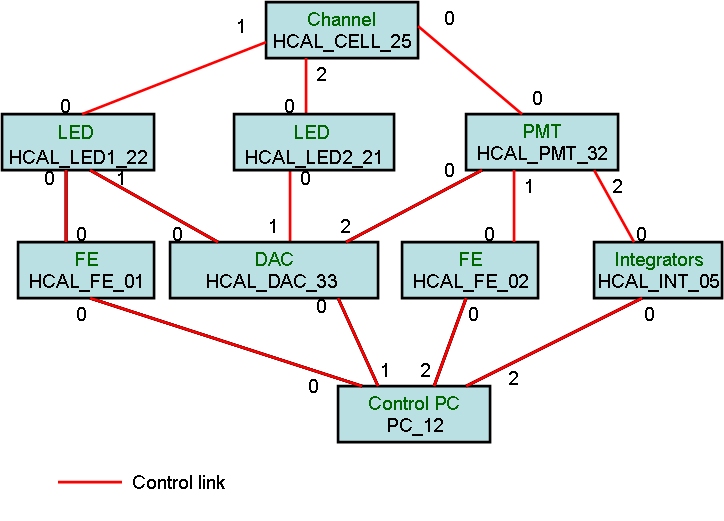
Things written in green correspond to the device type, things written in black correspond to functional names of devices.
The name you give must be meaningful for you and also not already used by another subsystem. That's you may want to prefix the device type if needed by the subsystem_name (using naming conventions). The C-library and its bindings are case-sensitive.
All these device types are part of the HCAL subsystem and only part of the HCAL subsystem.
Example of code to insert them using the C-library confDB
char hcal_device_type[7][100]={"HCAL_CHANNEL","HCAL_LED","HCAL_DAC","HCAL_INTEGRATOR","HCAL_FE","HCAL_PMT","HCAL_CONTROL_PC"};
int hcal_input_nb[7]={1,1,216,1400,2000,1000,4};
// max nb of inputs (you can put whatever, it's not used)
int hcal_output_nb[7]={1,3,20,20,20,1000,4};
// max nb of outputs (you can put whatever, it's not used)
char
hcal_rgbcolor_type[7][100]={"115,115,114","22,22,22","45,87,96","100,100,100","200,200,200","150,150,150","25,25,35"};
// color used for display if you view it in cdbVis, reference is rgb.
char hcal_description_type[6][100]={"also called
cell","led for hcal","dac board for the hcal","integrators for the hcal","fe
crates for hcal","pmt for hcal"," control pc for the hcal only"};
// some comments about the device type
for(i=0;i<6;i++)
{
if (i==0)
res_query=InsertMultipleDeviceTypes("HCAL",hcal_device_type[i],hcal_input_nb[i],hcal_output_nb[i],
hcal_description_type[i],hcal_rgbcolor_type[i],1, 0, ErrMess);
// to create the cache, first time of call
else
{
if(i==5)
res_query=InsertMultipleDeviceTypes("HCAL",hcal_device_type[i],hcal_input_nb[i],hcal_output_nb[i],
hcal_description_type[i],hcal_rgbcolor_type[i],0, 1, ErrMess);
// to insert and commit in the DB, last call
else
res_query=InsertMultipleDeviceTypes("HCAL",hcal_device_type[i],hcal_input_nb[i],hcal_output_nb[i],
hcal_description_type[i],hcal_rgbcolor_type[i],0, 0, ErrMess);
// to fill the cache
}
}
N.B all the functions described in this web pages are documented here
Then you have to list the functional device names with the serial nb associated with and group them by their device type.
Important : you have to determine whether your device will be considered as a host node (start or end you dataflow) or intermediate node.
In the example, devices of type "HCAL_CHANNEL" and "HCAL_CONTROL_PC" are host nodes (they start and end the dataflow chain). They are at the extremity of the connectivity schema.
The others are intermediate nodes.
Example of code to insert them using the C-library confDB
res_query=InsertMultipleFunctionalDevices("HCAL","HCAL_CELL_25","HCAL_CHANNEL",1,0,"XX112SA45","hcal_cell","lana,"nothing","HCAL_STATION_2","none,"1,0,ErrMess); // the fourth parameter indicates if it's a host node (1) or an intermediate node (0)
res_query=InsertMultipleFunctionalDevices("HCAL","HCAL_PMT_32","HCAL_PMT",0,0,"XX1145A45","hcal_pmt","lana,"nothing","HCAL_STATION_2","none",0,1,ErrMess);
In the example we have one type of link, control.
They are simple link, in the sense we have no link which carries both control and data.
Example of code to insert them using the C-library confDB
res_query=InsertSimpleLinkType("control_link",1,ErrMess); //use this function (instead of InsertMultipleLinkTypes) as we have only one insertion.
For each functional device used in the connectivity, insert all the port details.
In the example HCAL_CELL_25 has 3 ports. In our representation, they will be considered as outputs. Output and input are fixed using the data flow reference. Signals will be first detected by the HCAL_CHANNEL and go through the PMT, etc...
So the parameter port_way is set to 2. (if it's an input, port_way=1)
Port nb is a string, so you can put letter or special characters if needed.
Port type corresponds to the type of port : you are free to put something or not, for instance specs, analog, etc.
The (devicename, port_way, port_nb, port_type) identifies uniquely a port. Any duplication will raise an error.
Example of code to insert them using the C-library confDB
res_query=InsertMultiplePorts("HCAL_CELL_25","0",1,2,1000,0,"optical","","","","","","T",1,0,ErrMess);
//one for pmt, the fourth parameter indicates the port_way.
res_query=InsertMultiplePorts("HCAL_CELL_25","1",1,2,1000,0,"optical","","","","","","T",0,0,ErrMess);
// one for led1
res_query=InsertMultiplePorts("HCAL_CELL_25","2",1,2,1000,0,"optical","","","","","","T",0,1,ErrMess);
//one for led2
Important: For DAQ system, put "data" as port_type for the DATA network interface for TELL1 boards, Farm nodes and ODIN and "control" for the CONTROL network interface for TELL1 boards, Farm nodes and ODIN . Both of them written in lower case.
If ip aliases need to be inserted, use
5. List of links
Using the data flow reference, you insert the links. To determine if your link should be considered as bidirectional, do the following exercise.
First what kind of queries will you ask?
Second, if all my links are unidirectional, can i find all the paths i need? if yes, then your links are unidirectional, if not then put the links which allow you to get the missing paths as bidirectional
The picture below represents the connectivity of two channels
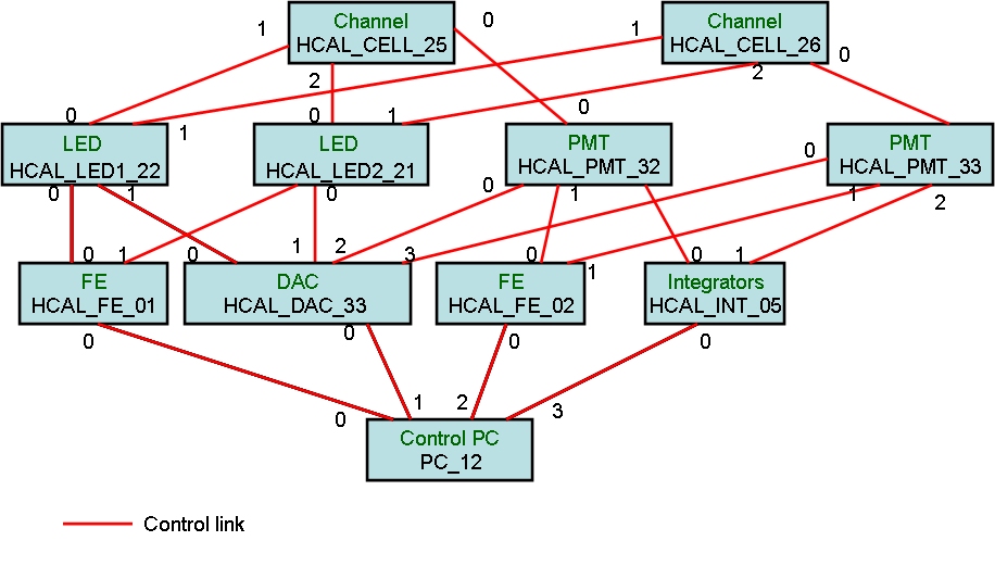
In our example, we want to know for instance the paths between HCAL_CELL_25 and HCAL_DAC_33, or between HCAL_DAC_33 and HCAL_CELL_25.
If the links are bidirectional, we will find many paths between HCAL_CELL_25 and HCAL_DAC_33, and most of them are not needed.
Don't forget that we have simplified the connectivity to one channel.... But if we restrict the links to unidirectional, we have all the paths.
That is the first one via HCAL_PMT_32, the second one via HCAL_LED1_22 and the last one via HCAL_LED2_21.
If the links were bidirectional, we would have paths such as HCAL_CELL_25, HCAL_LED1_22, HCAL_FE_01, HCAL_LED2_21,HCAL_DAC_33.
But we don't want this kind of path.
So the first type of query can be solved with links set to unidirectional.
The second type of query is quite similar except that we have reversed the destination and source.
However, we still need the same paths, i.e., via the PMT, the LED1 and via the LED2. Other paths must be rejected.
If you consider all the links unidirectional, from the Channel to the Control PC, it won't find the paths. However, if the algorithm doesn't find a path with the current flow, it reverses the flow of the connectivity, i.e. it will work with the same connectivity but the flow is now from the control PC to the channel.
Using this "automatic reverse flow", it is independent of the flow defined (from down to the top or from the top to the down).
The reason why you should reduce the number of bidirectional links, is that finding paths is NP-complete problem. The execution time can be very long if your connectivity is complex and if the number of links are high. So you add complexity if the link is bidirectional...
Example of code to insert them using the C-library confDB
// insert the links which start from HCAL_CELL_25
res_query=InsertMultipleMacroLinks("HCAL_CELL_25","HCAL_PMT_32","0","0","optical","optical","control_link","none",0,1,
0,ErrMess);
res_query=InsertMultipleMacroLinks("HCAL_CELL_25","HCAL_LED1_22","1","0","optical","optical","control_link","none",0,0,
0,ErrMess);
res_query=InsertMultipleMacroLinks("HCAL_CELL_25","HCAL_LED1_22","2","0","optical","optical","control_link","none",0,0,
1,ErrMess);