
|
|
Configuration Database Project |
| Home | Computing | DAQ | Notes | Meetings | Subsystems | Search |
Introduction:This page describes how to generate routing and destination tables using the connectivity information stored in the database. The first part defines key concepts used to generate routing and destination tables. The second part describes how connectivity has been modeled to provide all the required data to generate routing and destination tables. The last part explains the main idea behind the functions which constitute the package. Some definitions:Host node : device which processes data Switch or an intermediate node : device which transfers data without changing its content. When storing a new device in the database, there is an attribute "node" which has to be set to 1 if the device is a host node, 0 if not. Macroscopic link : group of one or more links between 2 devices. A macroscopic link is fully identified by the name of the 2 devices which compose the link. Microscopic link: a link between 2 ports of 2 devices. A microscopic is completely defined by the 2 couples (port number, devicename). We assume that all microscopic links between 2 devices have the same bidirectional link value (that is either all the microscopic links are bidirectional or unidirectional). We also assume the same link_terminated value (see second part for more details) Path: a sequence of macroscopic links which starts from a intermediate/host node and ends with a host node. Destination table: table containing all the possible host nodes that can be reached. Table RepresentationConnectivity table : representation of a link between 2 devicesFor each sub-system, we have a connectivity table with the following attributes: (the switch_from and the switch_to are completed regarding the dataflow of the system). |
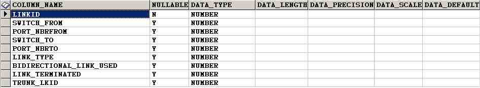
Fig.1 : Columns of the connectivity table
|
Link_type specifies the kind of data that the link (HLT, L1, data ...) carries. Link_terminated : 0 if the link is between 2 switches, 1 if switch_from is a host node and switch_to is a switch, 2 if switch_to is a host node and switch_from is a switch and 3 if switch_from is a host node and switch_to is a host node.(default value 0) Bidirectional_link-used : if the link is used as bidirectional link, 0 if not. (default value 0). Trunk_lkid : 0 if the link is not truncated (doesn't belong to an aggregated link) otherwise the linkid of the trunk_lkid. The connectivity table is completed by the user via a script or an graphical interface: switch_from,switch_to, port_nbfrom,port_nbrto, link_type, bidirectional_link_used (when not equals to the default value) and trunk_lkid (when not equal to the default value) must be provided by the user. Routing table package contentcreateNodeLink_tab function principles:This function generates 2 tables which can be used to create routing and or destination tables of any devices. NodeLink Table : Logical view of the connectivity of a systemThis table is dynamically created by the procedure createNodeLink_tab belonging to the routing_table_package. We have the following columns: |
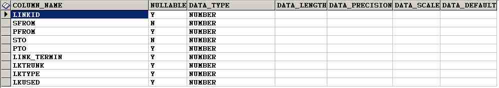
Fig.2 : Columns of the NodeLink table
|
This table stores the macroscopic links between devices: in other words, it's a kind of an upper view of the connectivity table. Let's consider the following schema: |
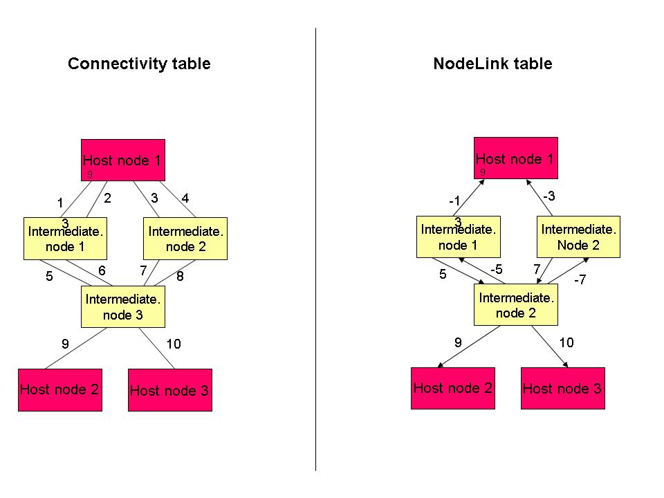
Fig.3 : Connectivity between devices
|
We select the minimun linkid of the microscopic links between 2 devices: it will be the linkid of the macroscopic link. Ex: Between intermediate node 1 and intermediate node 3, we have two links whose LinkIDs are 5 and 6. In the NodeLink table, we just store the link whose linkid is 5 (the smaller one). Then we check if the link is bidirectional. If yes, we store the reverse linkid too.(minus) Ex: Between intermediate node 1 and intermediate node 3, we have two bidrectional links whose LinkIDs are 5 and 6. In the NodeLink table, we store the link with the following entries (linkid=5, sfrom=intermediate node 1 and sto=intermediate node 3 and link_termin=0 because between 2 intermediate nodes) As the link is bidirectional we model it by inserting the following row : (linkid=-5, sfrom=intermediate node 3 and sto=intermediate node 1) Lkused specifies whether the link is used in the current configuration (1 yes, 0 no) Linkpertwo Table : Group of 2 linksThis table is dynamically created by the procedure createNodeLink_tab belonging to the routing_table_package. We have the following columns: |
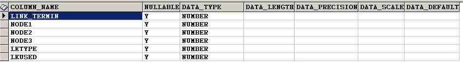
Fig.4 : Columns of the Linkpertwo table
|
After having created the NodeLink table, we generate the Linkpertwo table (always created together) which contains all possible set of two links. (just the linkid). The link_termin is the sum of the NodeLink_table.link_termin of lk1 (between node1 and node2) and lk2(between node2 and node3). Lkused specifies whether these group of 2 links are used in the current configuration (1 yes, 0 no) Ex: Referring to fig.3, we have the following row : link_termin=2 (0+2), lk1=5, lk2=9. We reject pairs of links which are similar to this schema : link_termin = 2+1 : it is because in this case, it means we have : a switch → a host node → a switch: A pair of links mustn't not cross a host node. NB: The link_termin of a path is always greater than 0 (either 1 or 2) with this representation.
CreatePathLinetab function principles (same comments for CreatePathLinetab_host) :This function creates the sysname_devfrom_11T table which have the following attributes: (it's the same function called for destination and routing tables). |
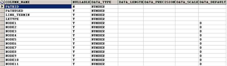
Fig.5 Columns of the sysname_devfrom_1 table
|
It creates a table whose name is sysname_devfrom_11T. This table contains all the possible paths that start from the given device and end to a host node. By default, the table is created it with 11 nodes ( common value of round_trip) If round_trip >10 we add node columns until node_roundtrip+1 pathused : indicates if the path is used in the current configuration (1 used, 0 not used) It also creates the sysname_devfrom_2RT (sysname_devfrom_2TD) table provided that the sysname_devfrom_11T table exists and if you want to generate routing tables (resp. destination table) afterwards. The body function consists of a loop: while (stop=0 and i<round_trip) loop Select possible links which can match the path of length i and of link_termin=0 Check that there is no cycle in the path (valid path or not) Insert the new valid paths found (of length i+1) in the sysname_devfrom_11T table: Delete the rows where link_termin=0 and linki+1=0 (old rows) Insert the new valid paths found (of length i+1) in the sysname_devfrom_2RT (or sysname_devfrom_2TD ) table: Count the number of link_termin=0. If all the link_termin > 0 then stop=1; end loop; return i+1; (which corresponds to the maximum length of a path found)
|
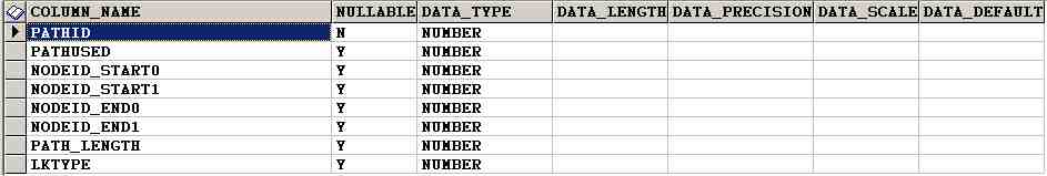
Fig.6 Columns of the sysname_devfrom_2RT (sysname_devfrom_2TD) same for table
|
The body function selects the shortest path for each host node reachable from the sysname_devfrom_1 table pathid : pathid of the shortest path (same value as the one in sysname_devfrom_1 to enable us to constitute the whole path) pathused: indicates if the path is used in the current configuration (1 used, 0 not used) linkid_start: Link ID of the first link of the path (corresponds to the link1 column of the sysname_devfrom_1 table) linkid_end : Link ID of the last link of the path. path_length: length of the path: (linkid_end corresponds to the linkpath_length column of the sysname_devfrom_1 table) createRoutingTable_SP principlesThis function creates the routing table from the sysname_devfrom_2RT table. Execute it after calling createPathLineTab function or if you want to regenerate the routing table. The routing table has the following columns: |
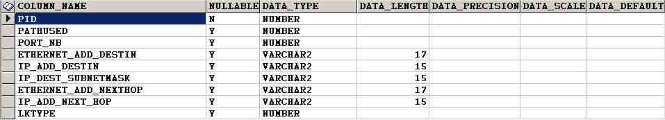
Fig.7 Columns of the sysname_devfrom_3RT table
|
pid represents the path ID of the path and pathused indicates if the path is used in the current configuration (1 used, 0 not used) From this table we can have both the IP routing table or the MAC address (the kind of the table depends on the type of the switch). It's up to the user to select the columns needed. All the information regarding Ethernet and IP addresses are stored in a table called sysname_ip_ethernet.
createTabDestinThis function generates the sysname_devfrom_3TD table from the sysname_devfrom_2TD table. The table looks like : |
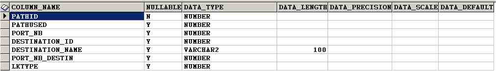
Fig.8 columns of the sysname_devfrom_3TD
|
The body of the function consists of selecting the different couples (device port number , reachable host nodes) from the sysname_devfrom_2TD table. Trigger to update all these tablesWhen you update the connectivity table or you delete/insert a row in the connectivity, a trigger is fired to update the nodelink and linkpertwo tables. Then it regenerates all the tables which have been created by the routing_table_package and have been affected by the changes. So what I'd advise the user to disable the trigger if he intends to perform a lot of changes and enable it at the very last changes. It will gain in performance. The command to disable a trigger is the following : alter trigger trigger_name disable (/enable)
PL/SQL functions to get the deviceID/device Name of a given device: GiveDeviceName(deviceid number ,sysname varchar2) : function which gives the device name. GiveDeviceID(devicename varchar2 ,sysname varchar2): function which gives the deviceID |