|
PVSS |
| Home | Computing | Notes | Meetings | Subsystems | Search |
WinCC-OA (ex PVSS II) Introduction for Newcomers
Introduction
PVSS II is a SCADA system. SCADA stands for Supervisory Control and Data Acquisition. PVSS will be used to connect to hardware (or software) devices, acquire the data they produce and use it for their supervision, i.e. to monitor their behavior and to initialize, configure and operate them. In order to do this PVSS provides the following main components and tools:
A run time database
Where the data coming from the devices is stored, and can be accessed for
processing, visualization, etc. purposes.
Archiving
Data in the run-time database can be archived for long term storage, and
retrieved later by user interfaces or other processes.
Alarm Generation & Handling
Alarms can be generated by defining conditions applying to new data
arriving to PVSS. The alarms are stored in an alarm database and can be
selectively displayed by an Alarm display. Alarms can also be filtered,
summarized, etc.
A Graphical Editor
Allowing users to design and implement their own user interfaces
A Scripting Language
Allows users to interact with the data stored in the database, either from
a user interface or from a “background” process. PVSS scripts are called
CTRL (read control) scripts.
A Graphical Parameterization tool
Allowing users to:
Define the structure of the database
Define which data should be archived
Define which data, if any, coming from a device should generate alarms
etc.
Architecture
PVSS has a highly distributed architecture. A PVSS application is composed of several processes, in PVSS nomenclature: Managers.
A typical PVSS application is composed of the following Managers:
The Event Manager (EVM) – is responsible for all communications. It receives data from any Drivers (D) and stores it in the data base.
The Data Base Manager (DBM) – provides the interface to the (run-time) data base.
User Interface Managers (UIM) – can get device data from the database, or send data to the database to be sent to the devices, they can also request to keep an “open” connection to the database and be informed (for example to update the screen) when new data arrives from a device.
Ctrl Managers (Ctrl) – provide for any data processing as “background” processes, by running a scripting language. This language is like “C” with extensions.
API Managers (API) – Allow users to write their own programs in C++ using a PVSS API (Application Programming Interface) to access the data in the database.
Drivers (D) – Provide the interface to the devices to be controlled. These can be PVSS provided drivers like Profibus, OPC, etc. these will be described later in more detail, or user-made drivers.
A PVSS System is an application containing one data base manager and one event manager and any number of drivers, user interfaces, etc.
PVSS Managers can run on Windows or Linux and they can all run in the same machine or be distributed across different machines (including mixed Windows and Linux environments). When the managers run distributed across different machines this is called a PVSS Scattered System.
PVSS can provide for very large
applications, in which case one PVSS system would not be enough. In this case a
PVSS Distributed System can be used.
A distributed system is built by adding a Distribution Manager (Dist) to each
system and connecting them together. Hundreds of systems can be connected in
this way.
Database Structure – The Datapoint Concept
The device data in the PVSS database is structured as, so called, DataPoints (DP) of a pre-defined DataPoint Type(DPT). PVSS allows devices to be modelled using these DPTs/DPs. As such it allows all data associated with a particular device to be grouped together rather than being held in separate variables (as is typical in many SCADA systems.)
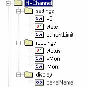
A DPT describes the data structure of the device and a DP contains the information related to a particular instance of such a device. The DPT structure is user definable and can be as complex as one requires and may also be hierarchical as shown in the example. In the example figure we see a DPT representing a simple high voltage channel. This has a set of read (readings) and write (settings) parameters, called Data Point Elements (DPEs) associated with it as well as associated display information - in this case the name of the panel to be used
After defining the datapoint type, the user can then create datapoints of that type which will hold the data of each particular device.
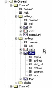
Below we see two instances of this DPT called Channel1 and Channel2. For Channel1 we can see that for the vMon parameter a number of sub-elements are present (alert_hdl, archive, address, original, common and lock). These are known as ‘configs’ and enable specific behaviour to be configured for a DPE e.g. alarm handling or archiving as well as to hold attributes of that DPE e.g. its current value or its hardware address.
In this example the datapoint elements
mapping to the device data are only of types float, boolean and string but
several more data types are available. In particular dynamic arrays of
the simple data types, like dyn_int, dyn_float, dyn_string, etc.
Dynamic arrays can hold a variable number of elements of the same type.
Datapoint elements can also contain references to other datapoints or dynamic
arrays of such references.
In order to access the data of a particular
element of a datapoint, for example a channel’s vMon, the user can address it
as:
Channel1.readings.vMon
The creation and modification of DPTs and DPs can be done either using the Graphical Parametrization tool, or programmatically using ctrl scripts.
Building User Interfaces
PVSS allows users to design their own user interfaces, in a “drag and drop” fashion. For that a special User Interface Manager – the Graphic Editor – can be started.
By using the Graphic Editor (example above) , the user can first design the static part of a panel, by placing widgets like buttons, tables, plots (called trends in PVSS), etc. Actions can then be attached to each widget. Depending on the widget type actions can be triggered on Initialization, user click or double click, text input, etc.
Actions are programmed using PVSS’s scripting language, i.e. by means of CTRL scripts (see next section).
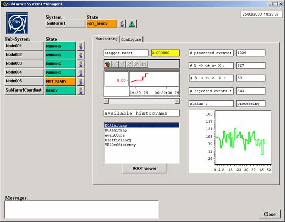
The Following is a PVSS panel containing an example of a plot, an histogram and several other widgets like buttons and textfields.
The same panel or graphic symbol may be required many times in a controls application. To ease development PVSS provides the possibility to create a single symbol or panel and to use it many times. This is called a Reference Panel. Changes to this Reference Panel are inherited by all instances of the panel. Where actual variables, which vary between the various instances, are referred to in such a Reference Panel, these are replaced by variables called $parameters. When the Reference Panel is instantiated these $parameters are replaced by the appropriate actual variable names. This can be done either during development time when a Reference Panel is embedded into another panel or at run-time when the panel is opened. In this latter case the required variable names are passed as arguments when opening the panel.
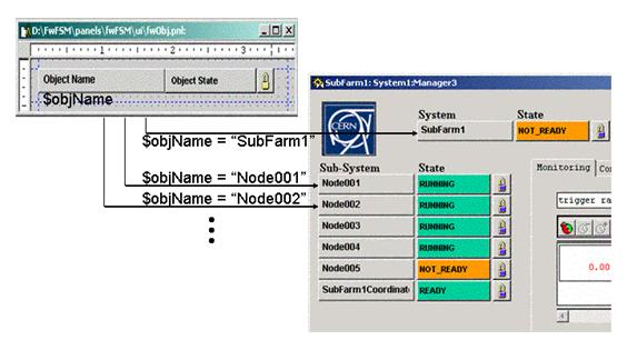
In the example above one $parameter is used in order to pass the name of the object to be displayed. The name is then used inside the reference panel to get from the database the rest of the information related to the object, like its state, etc.
Using Control Scripts
PVSS Ctrl Scripts can be used in panels or as stand-alone processes. They provide the interface to the PVSS database. These scripts comply to the “C” syntax but they contain extensions, in particular new variable types, like “string”, and the provision for dynamic arrays.
PVSS provides a very large library of functions giving access to all PVSS functionality and more. There are functions for datapoint manipulation, for graphics, for file acces, etc.
The three most important functions in terms of datapoint access are:
The two most important functions in terms of graphical functionality are:
The complete set of functions is described in detail in the Online Help under the section “CONTROL”
As an example, in order to put in a panel a “Text Field” widget permanently showing the contents of a data point element (lets take our Channel1’s vMon), one would attach to the widget’s “EventInitialize” the following script:
main()
{
// request that a callback be executed when contents of
datapoint element vMon change
dpConnect(“updateCallback”, ”Channel1.readings.vMon”);
}
updateCallback(string dpName, float newValue)
{
// set this widget’s text property to the new vMon value
setValue(“”, ”text”, newValue);
}
Another example could be to read the value of a TextField widget and set it as Channel1’s v0 when the user clicks on an apply button. For this one would attach to the “EventClick” of the Apply button widget the following script:
main()
{
float newValue;
// read the value of the v0 TextField widget
getValue(“v0TextField”, ”text”, newValue);
// set the value of datapoint element v0 to the new value
dpSet(”Channel1.settings.v0”, newValue);
}
As mentioned before scripts don’t have to be attached to panels, they can run in stand-alone mode. As an example we can permanently run a script that for example switches off the channel (by writing 0 to the settings.state element) if its vMon exceeds a certain value.
main()
{
// request that a callback be executed when contents of
datapoint element vMon change
dpConnect(“updateCallback”, ”Channel1.readings.vMon”);
}
updateCallback(string dpName, float newValue)
{
// Check if vMON is higher than 500 volt
if(newValue > 500)
{
// Switch the channel off
dpSet(”Channel1.settings.state”, 0);
}
}
Any user functions that are repeatedly needed can be stored in libraries for use by panels and scripts. A script library is no more that a file containing the different functions and stored in a specific directory of a PVSS project.
Accessing Devices
In all the above examples we are assuming that our High Voltage Channel was connected to real hardware, i.e. we supposed that vMon was being updated and that when we wrote to v0 or state the data was sent to the channel. In order for this to be a valid assumption we now have to connect the datapoint elements in our database to real hardware (or software). This connection mechanism will depend on the type of the device that is being used.
PVSS provides several drivers to connect to various types of hardware or to different communication protocols. The type of protocol to use can be configured using the Parametrization tool by selecting the address config of the relevant data point element.
The OPC Protocol
For our purposes there is basically only one of the PVSS provided drivers which is of relevance, this is the OPC protocol driver, i.e. PVSS provides a generic OPC client.
Several industry HW manufacturers provide an OPC server. An OPC server is an abstraction layer between the real hardware and the user. For example a device, lets say a high voltage power supply could be read-out via CAN bus trough a PCI card on a given PC. Instead of a user having to:
read the power supply documentation to find out what registers and what bits in these registers he has to read or write in order to perform the operation he wants
study the CANbus documentation and learn the CANbus protocol in order to be able to read or write the above registers via CAN
Read the documentation of this specific PCI CANbus master card to see what libraries are available (assuming there are some) to perform CAN bus operations, in order to integrate them in his own program.
An OPC server implements all this and provides as a set of OPC items the data available from the hardware and the commands it can receive. In the example of a power supply it will provide parameters like: PowerSupply1.Channel1.vMon, etc.
OPC items are in a way very similar to our datapoint elements, so all we have to do is in the address config of the data point element, after choosing OPC as a protocol, define which OPC item it connects to.
Several vendors of HW commonly used in Physics experiments, are now providing OPC servers for their equipment. This is the case of CAEN, WIENER and ISEG which provide OPC servers for their various types of power supplies.
Also the Atlas ELMB (Embedded Local Monitoring Box) a radiation tolerant device for analog and digital IO provides an OPC server.
The DIM Protocol
OPC servers, although very easy to use, are quite complex to develop. So we do not encourage users to write their own OPC server for commercial equipment not providing one or for home made equipment.
For this purpose the DIM protocol has been integrated into PVSS. DIM is also a client/server protocol and it provides a similar abstraction layer. Except that this time the equipment expert will have to write also the server part.
DIM servers provide DIM services which are similar to OPC items.
A PVSS DIM client provides the mechanism to connect to the server. As for OPC, the user will have to define the correspondence between datapoint elements and DIM services. Since DIM services can be structures containing different types of data, correspondence can be made between a DIM service and a full datapoint containing several elements. This correspondence can be made graphically or by using control scripts.
The full description of how to use the PVSS-DIM toolkit is available here.
The JCOP Framework
The JCOP Framework is being developed in common for the four LHC experiments, with contributions from the experiments themselves and the IT/CO group at CERN.
This framework is based on PVSSII and provides guidelines, components and tools for the different teams to build their control applications in a coherent manner.
The framework provides complete components for commonly used equipment. Complete meaning: any necessary OPC or DIM servers, the PVSS definitions in terms of datapoints types and datapoints, any control scripts and script libraries and all panels necessary to configure and operate the device.
At the moment the complete devices available in the framework are: CAEN high voltage power supplies, WIENER crates (power supplies and fan trays) and low voltage power supplies, ISEG high voltage power supplies and the Atlas ELMB.
For these components the user will not have to know anything about PVSS or OPC, he just has to configure the system, i.e. specify what devices he has and their characteristics (number of channels, etc.), all this is done by pointing and clicking.
The framework also offers tools for users to integrate their own devices, like the PVSS-DIM toolkit, and some reference panels and script libraries that can be used in order to build a new device.
Other tools available include visualization tools, allowing users to define pages of plots, etc.
The documentation about the JCOP Framework and its components is available here.
Another large component of the framework, although not completely integrated yet, is a tool to build hierarchies of components based on a Finite State Machine – the Controls Hierarchy. This tool allows users to define the desired behaviour of groups of components and to take actions and recover errors based on their states or on the states of external elements.
It also allows the various components to be partitioned in and out of the system in order to work in stand-alone mode. In the final system all devices in the experiment will be under the supervision of this tool.
Documentation concerning the Controls Hierarchy is available here.
Related Information
WinCC-OA Installation:
https://readthedocs.web.cern.ch/display/ICKB/WinCC-OA+Service/
JCOP Framework page:
http://jcop.web.cern.ch/jcop-framework