|
|
D2DCS RACKS LAYOUT |
|
|
D2DCS RACKS LAYOUT |
|
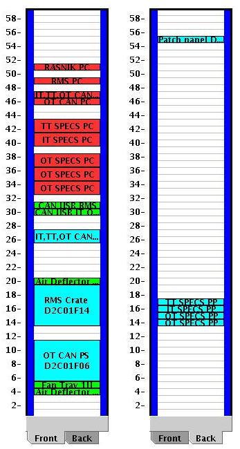
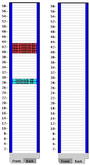
D2DCS Racks layout extract from RackWizard: In D2 barracks, there's 4 racks defined for DCS: D2C01 to D2C04. These racks house the so-called DCS-PCs, which are the interfaces for the slow-control of detector elements via SPECS, CAN and a few others, located on either side of the wall. Each rack contains a CAN-powersupply to provide power to CAN-buses, which require this. There are two types of PCs in this rack:
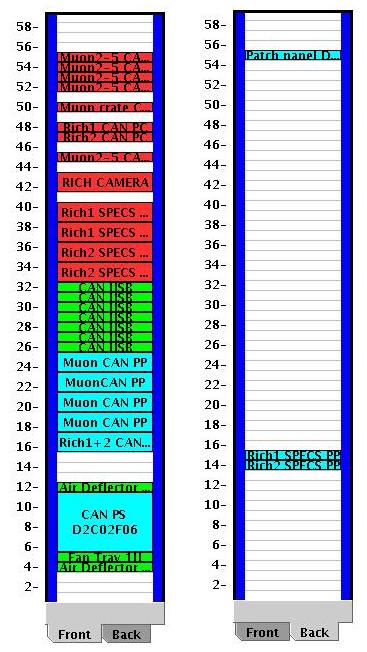
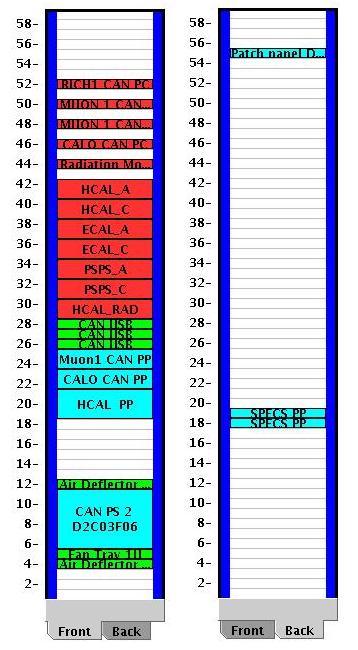
The following EDMS document describe what is already entered into Rackwizard inventory database: https://edms.cern.ch/document/750091/1 You can find bellow a short summary of this technical note, with the rackwizard drawings of those 4 racks: For the slow-control in DCS racks, 2 main type of links are used: SPECS and CAN ( with 2 kinds of CAN: powered and not powered buses ). SPECS links are attached on the back of the racks to a SPECS patch panel ( 1U high ). One SPECS patch panel can receive 24 links and used RJ45 ports for patching. CAN links which don't need remote powering are connected to a CAN patch panel ( 2 U high ), each CAN PP can provide 16 DB9 connections. CAN which required remote powering are connected to a CAN PS ( Power Supply ) crate ( 6 U high ). A crate can contain up to 8 modules with each 2 channel, consequently 1 crate can provide 16 powered CAN buses. Interfacing between control PCs and slow control links are also of 2 types: PCI SPECS master card and CAN USB modules ( 1U high ). PCI SPECS MASTER card are located into the 2U control PC. Each card contains 4 RJ45 ports, and 1 control PC can receive 3 PCI master cards ( 12 RJ45 SPECS links ). Then a patch cord is used to connect to the SPECS patch panel. CAN USB MASTER modules are 1 U devices placed between control PC and CAN patch panels on the racks front face .Each single 1U device contains 2 independents CAN MASTER USB with each 1 USB port ( to connect to the 1U control PC via a USB patch cord ) and 8 DB9 port ( CAN buses patch cord will be used to link the CAN MASTER USB to CAN patch panels or CAN PS crates ). On these views, control PC are in red, CAN ,SPECS and Network patch panels in blue, and CAN module in green. Rack D2C01: IT TT OT Rack D2C02: RICH 1 + 2 - MUON S2-5
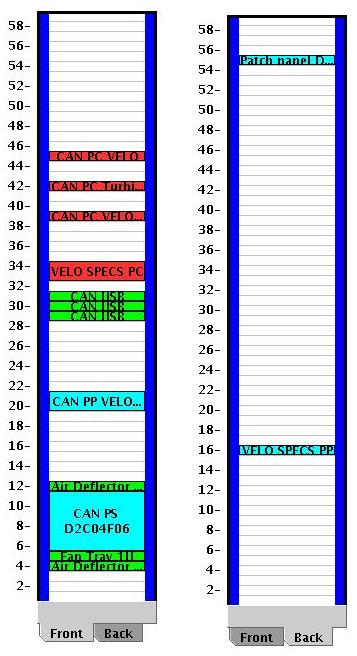
Rack D2C03: CALO - MUON Rack D2C04: VELO + Others In addition to these 4 DCS slow control racks, 2 others are hosting "DCS" control PC with a direct ethernet link from the PC nic to remotely managed device. They are D2C06 and D2C07. Outer tracker Maraton power supply crates for HV/LV are controlled this way with 4 1U PC that sit into D2C06. Additional control PC will sit into these racks but information is not available yet. Rack D2C06:
If you need more information and details about the content of DCS racks, please consult EDMS note: D2DCS RACKS LAYOUT at https://edms.cern.ch/document/750091/1
|
| And for a complete and detailed view of these racks, you can read-only login to Rackwizard: |
|
|
This page last edited by G.M on March 19, 2007 .